
Ipkblsr 35w Schematic -
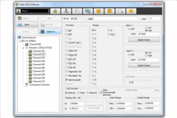
Simply connect your 2638A, 1586A, NetDAQ or 2680A Series to your computer and your current hard¬ware configuration will pre-populate in the configuration setup area, ready to edit if needed.


Simply connect your 2638A, 1586A, NetDAQ or 2680A Series to your computer and your current hard¬ware configuration will pre-populate in the configuration setup area, ready to edit if needed.
If you are currently debugging this board, what specific symptoms are you seeing? Let me know if you need help , locating the BIOS clear pads , or troubleshooting a particular power rail , and I can provide further technical steps. Share public link
Understanding the IPKBL SR 35W schematic is indispensable for troubleshooting and repair. Common issues might include:
The standard architecture of a 35W power design relies on a Switch-Mode Power Supply (SMPS) topology. To maximize efficiency while keeping the footprint compact, these circuits typically employ a High-Frequency Flyback Converter or a Gallium Nitride (GaN) power stage.
(for custom projects)
Are you dealing with a , or is this a DC-to-DC buck-boost converter circuit? Share public link
If you are currently engineering a power delivery system based on this layout, please share the (e.g., 5V, 9V, 15V, 20V) or your preferred PCB design software (e.g., KiCad, Altium Designer). This information will allow for a more precise analysis of the protocol controller configurations and trace width calculations. Share public link
If you are currently debugging this board, what specific symptoms are you seeing? Let me know if you need help , locating the BIOS clear pads , or troubleshooting a particular power rail , and I can provide further technical steps. Share public link
Understanding the IPKBL SR 35W schematic is indispensable for troubleshooting and repair. Common issues might include: ipkblsr 35w schematic
The standard architecture of a 35W power design relies on a Switch-Mode Power Supply (SMPS) topology. To maximize efficiency while keeping the footprint compact, these circuits typically employ a High-Frequency Flyback Converter or a Gallium Nitride (GaN) power stage. If you are currently debugging this board, what
(for custom projects)
Are you dealing with a , or is this a DC-to-DC buck-boost converter circuit? Share public link Common issues might include: The standard architecture of
If you are currently engineering a power delivery system based on this layout, please share the (e.g., 5V, 9V, 15V, 20V) or your preferred PCB design software (e.g., KiCad, Altium Designer). This information will allow for a more precise analysis of the protocol controller configurations and trace width calculations. Share public link